
Measuring AC mains voltage safely with a microcontroller like Arduino can be challenging because mains voltage is high and dangerous, while Arduino can only read low analog voltages (0–5 V).
That’s where the ZMPT101B AC Voltage Sensor Module comes in. It is an isolated voltage transformer module designed specifically for AC voltage measurement with microcontrollers.
In this tutorial, you’ll learn how to:
- Measure AC voltage using Arduino
- Interface the ZMPT101B sensor
- Calibrate readings
- Display voltage on Serial Monitor
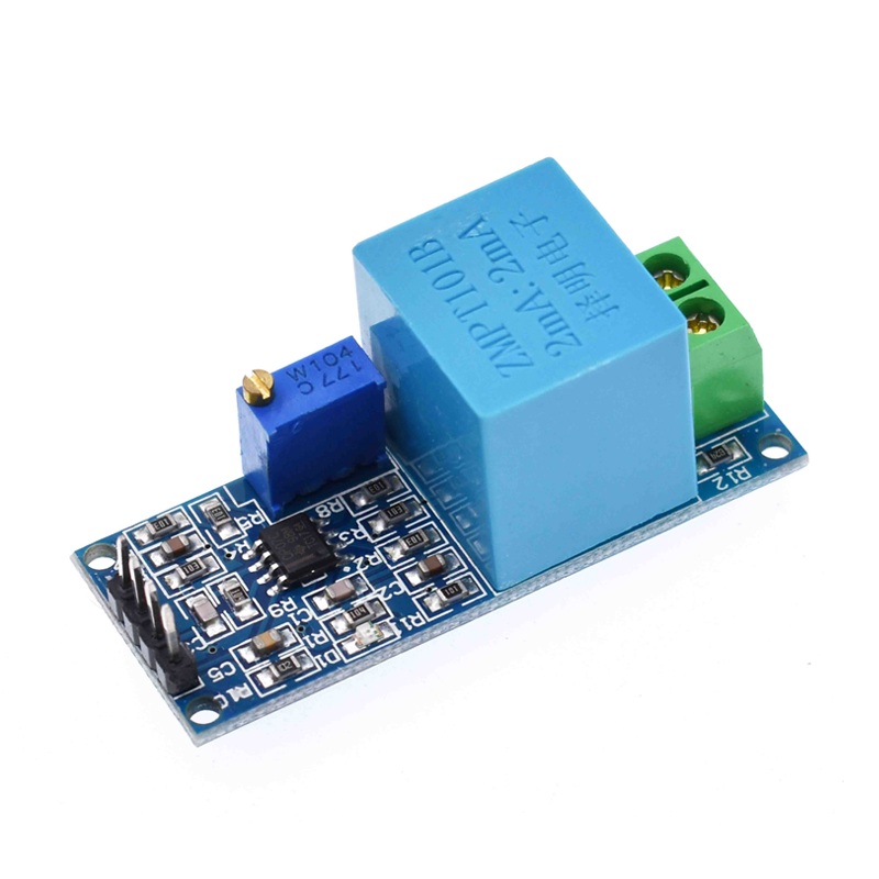
What is the ZMPT101B AC Voltage Sensor?
The ZMPT101B is a precision voltage transformer module used to measure AC voltage while providing electrical isolation between high-voltage AC and low-voltage electronics.
Key Features:
- Measures AC voltage up to 250 V AC
- Built-in isolation transformer
- Adjustable gain (trimmer potentiometer)
- Analog output compatible with Arduino
- High accuracy & linearity
In simple words: It converts dangerous AC voltage → safe small analog signal.
How the Sensor Works
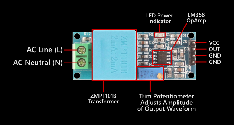
The module contains:
- Precision voltage transformer
- Operational amplifier
- Gain adjustment potentiometer
Process:
- AC voltage enters transformer
- Transformer scales voltage down
- Op-amp amplifies signal
- Arduino reads analog waveform
- Software calculates RMS voltage
Components Required
- Arduino Uno / Nano
- ZMPT101B AC Voltage Sensor Module
- AC source (mains or AC adapter)
- Jumper wires
- Breadboard (optional)
⚠️ Safety Note: If using mains AC (230 V), be extremely careful. Prefer testing with an isolated AC source or adapter.
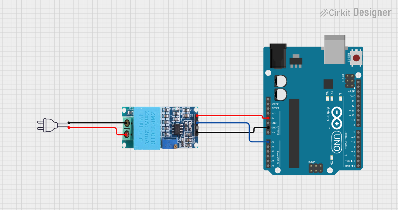
Wiring Diagram
ZMPT101B → Arduino Connections:
| ZMPT101B | Arduino |
|---|---|
| VCC | 5V |
| GND | GND |
| OUT | A0 |
| AC Input | AC Source (Live & Neutral) |
Arduino Code to Measure AC Voltage
const int sensorPin = A0;
float calibrationFactor = 0.5;  // adjust during calibration

void setup() {
  Serial.begin(9600);
}

void loop() {
  int maxValue = 0;
  int minValue = 1023;

  // sample waveform for 100 ms
  unsigned long start = millis();
  while (millis() - start < 100) {
    int value = analogRead(sensorPin);
    if (value > maxValue) maxValue = value;
    if (value < minValue) minValue = value;
  }

  float peakToPeak = maxValue - minValue;
  float voltage = (peakToPeak * 5.0 / 1023.0) * calibrationFactor;

  Serial.print("AC Voltage: ");
  Serial.print(voltage);
  Serial.println(" V");

  delay(500);
}
Calibration (Important Step)
Every ZMPT101B module has slightly different gain. You must calibrate it for accurate readings.
Steps:
- Measure mains voltage with multimeter (Example: 230 V)
- Run Arduino code (Example reading: 210 V)
- Adjust:
- Turn onboard potentiometer, OR
- Change
calibrationFactor
- Until readings match.
Understanding the Output
The sensor outputs a scaled AC waveform centered around 2.5 V. Arduino samples waveform → calculates peak-to-peak → converts to RMS voltage.
RMS formula used: Vrms = Vpeak / √2
The calibration factor internally accounts for this conversion.
Safety Precautions
- Never touch AC terminals while powered
- Use insulated wires
- Prefer isolation transformer for testing
- Keep Arduino powered via USB, not mains
- Do not connect Arduino ground to mains
Applications
- Smart energy meters
- Voltage monitoring systems
- Home automation
- UPS monitoring
- IoT power logging
- Over/under-voltage protection
Possible Improvements
You can enhance this project by adding:
- LCD/OLED display
- IoT logging (ESP8266)
- Over-voltage alarm
- Data graphing
- RMS calculation library
- Calibration UI
Conclusion
The ZMPT101B module makes AC voltage measurement with Arduino safe, isolated, and accurate. With simple wiring and calibration, you can build your own voltage monitoring system for electronics or IoT projects.